ARDUINO ETHERNET REMOTE CONTROL OF LED FROM MOBILE PHONE

The purpose of this project is to show some practical coding including how to modify a standard Arduino sketch to do something extra – in this case controlling a LED from a mobile phone. It also shows how to write a simple web page in html. The original objective was a school example supporting STEM (Science Technology Engineering and Maths). This can be completed in 45 mins with the students doing all the actions/coding. It should also inspire confidence both in writing html/webpages and adapting standard Arduino code to achieve a new task.
This does not require any special apps for the phone or signing up to any service – It just uses the standard (free) Arduino code plus some new code, shown here, to enable it to control the LED.
You will need:
1 Arduino UNO or other type as long as it has the standard connection layout for shields, plus USB cable
2 Ethernet Shield and Ethernet cable
3 LED and resistor (suggest 180ohms with white or blue LED and 330ohms with Red, Yellow or Green LED)
4 Wireless router
5 PC/laptop
6 Mobile phone (can use the PC/laptop instead)
Preparation
Download the Arduino IDE (integrated development environment) from: https://www.arduino.cc/en/Main/Software
Overview/How it works
The Arduino serves a webpage with a button. Users can log onto the webpage and click the button. Code in the Arduino detects this and turns the LED on or off as directed.
The starting point the standard Arduino webserver sketch – that can be logged onto to see a webpage.
We then write our own simple webpage with a button that will control the LED.
Then we put the two together so the Arduino serves our webpage and add some code so we can drive the LED.
Write Our Web Page
We can use Windows Notepad to do this. I prefer Notepad++ (Google for free download) as it makes the code easier to read.
Webpages use the html language where instructions are set in pairs e.g.
<body> ..... </body>
with relevant code sandwiched in between.
Type out the following or download LED.txt
<!!DOCTYPE html>

<html>

<head>

<title> LED Control </title>

</head>

<body>

<h1>LED Control</h1>

<form method = 'get'>

<button name = 'LED' type = 'submit' value = 'On'>Turn LED On

</form>

</body>

</html>
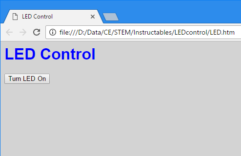
Save as led.htm . Then test it by double clicking the file. It should load in the default browser. At this stage the button will not do anything.
The code can be modified using reference to one of the many html guides. For now just add the text to the 'body' statement so it looks like:
<body style='background-color:lightgrey'>
And see in what way the page changes.
Get the Standard Arduino Webserver Sketch Working
It is always good to start from something that works.
Connect the Arduino to a PC via USB and the router via Ethernet, and start the Arduino IDE. Click File>Examples>Ethernet>Webserver. A new page will appear with the code.
In most cases the code will work as is. The IP address and mac address have been fixed to arbitrary numbers – that must be unique on the local network. The IP address is seen in the line:
IPAddress ip(192, 168, 1, 177);
These are usually allocated in order starting at 192.168.1.0 . On a home network it is unlikely that 177 devices will have been allocated. A clash is more likely on larger systems – e.g. schools (and hence I bring a router with me when doing this project).
A clash of mac address is very unlikely as these are very big numbers. The most likely cause being another Arduino running an Ethernet example (in which case just change the number in the code).
On some routers the IP address will need to be changed to e.g. 192.168.2.177. The key is that the the first 3 numbers should be the same as the router logon IP address, usually found on the router.
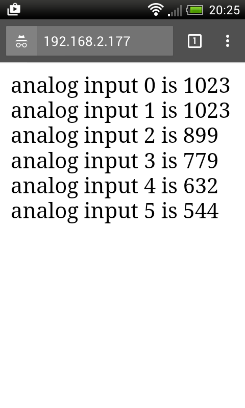
Now press the load button on the Arduino IDE (right arrow). This will first compile the sketch into machine code and then, if there are no errors, download it to the Arduino. Now connect the phone to the wireless router (if not already connected) or open a browser on the PC that has a router connection and enter the Arduino IP address as the four numbers, separated by full stops – e.g. 192.168.1.177 and the Arduino page should appear as below.
Also you can open the serial monitor to see diagnostic information from the sketch. On the IDE click Tools>Serial Monitor and if necessary set the baud to 9600 (bottom right). This shows all the data from the serial.write() instructions.
For interest- every website has its own IP address. When one sends a website name from a browser this is picked up by directory that looks up the IP address for the website name so the request to log on is sent to the right place.
Modify the Arduino Sketch
The first mod to do is to change the webpage.
This is served by a series of lines all starting client.println.
Delete everything between:
client.println("<html>");And
client.println("</html>");We now want our new html code between
<html>
and
</html>
as a series of client.println statements. Easiest approach is to copy and paste the html code between these and then use copy and paste to insert client.println(“ at the start of each line and “); to the end.
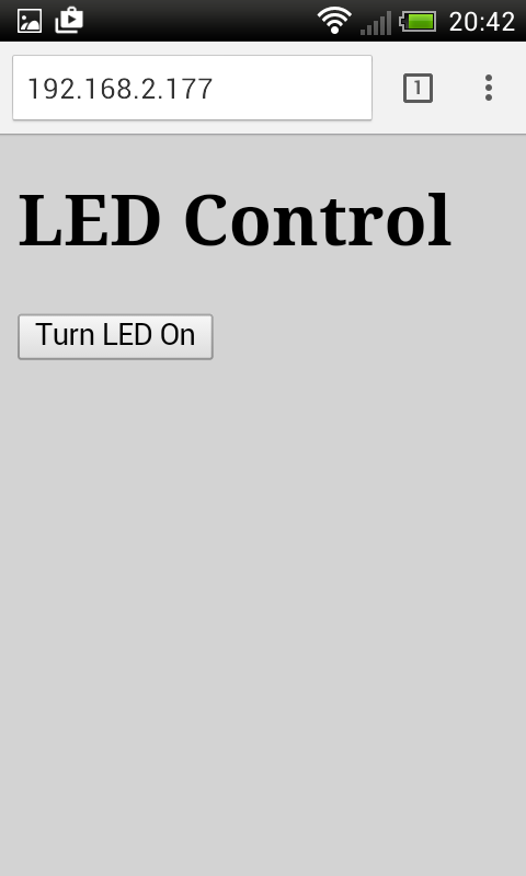
Now download this and test it as in Step2. Our page should appear as below.
Enabling the driving of the LED just needs the connection pin to be set as OUTPUT (rather than INPUT). So within setup() add the code:
pinMode(2,OUTPUT); // LED on pin 2
Note the // and any text after it is ignored by the compiler. However these comments make it easier to understand the code.
We need a couple of extra variables. One for the LED status and one to collect the http request (to see if the button was clicked). So before setup() add:
String HTTP_req;                         //store for http request

boolean LED_status = 0;                  //LED status, 0 =off
A String variable is a line of text. A boolean is a logical – on/off or 1/0 variable.
We need to store the http request that comes in a character at a time (string variable c). Add after serial.write(c);
HTTP_req +=c; //add character in c to end of HTTP_req string
Now add some lines to drive the LED and modify the webpage to show the LED as on or off. Add these after the ‘if’ statement that detects the end of the HTTP request ( if (c == '\n' && currentLineIsBlank) { )
if(HPPT_req.indexOf("LED=On")>-1) {             //see if checkbox was clicked

    LED_status=1;
}
if(HPPT_req.indexOf("LED=Off")>-1) {            //see if checkbox was clicked
    LED_status=0;
}
We need to change the webpage to reflect the LED status. So replace the line:
client.println("<button name='LED' type ='submit' value='On'>Turn LED On");With:
if(LED_status) {

   digitalWrite(2,HIGH);                              // switch LED on
   client.println("<button name='LED' type ='submit' value='Off'>Turn LED Off");

}
else {
   digitalWrite(2,LOW);                                // switch LED off
   client.println("<button name='LED' type ='submit' value='On'>Turn LED On");

}
And lastly we need to empty the HTTP string when we are done. So add before the’ break’ statement:
HTTP_req = ""; // finished with request, so empty string
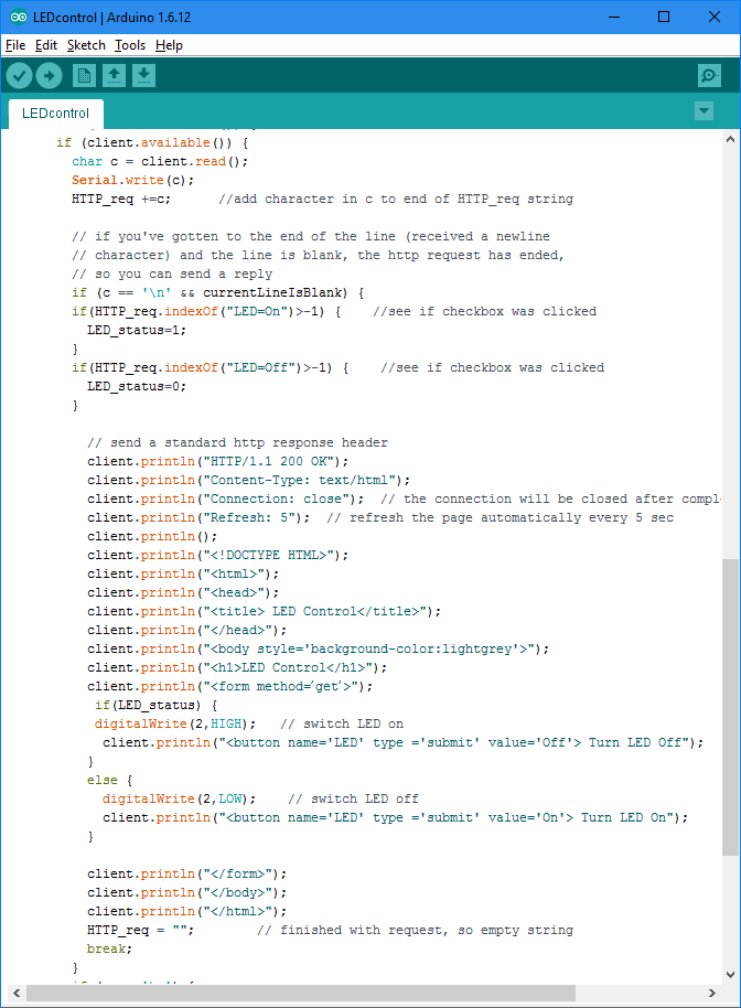
The section of modified code should now look like the screenshot below or you can download the whole sketch from here (note may need to change the IP address).
Give It a Test
We still have to connect the LED. This should have the resistor connected between digital pin 2 and the LED anode, and the LED cathode connect to 0v/GND.
With the Arduino still connected load the code (press the right arrow icon). Now log onto the Arduino from the phone/PC as in step 2 and try clicking the button. It should all go like the video below.