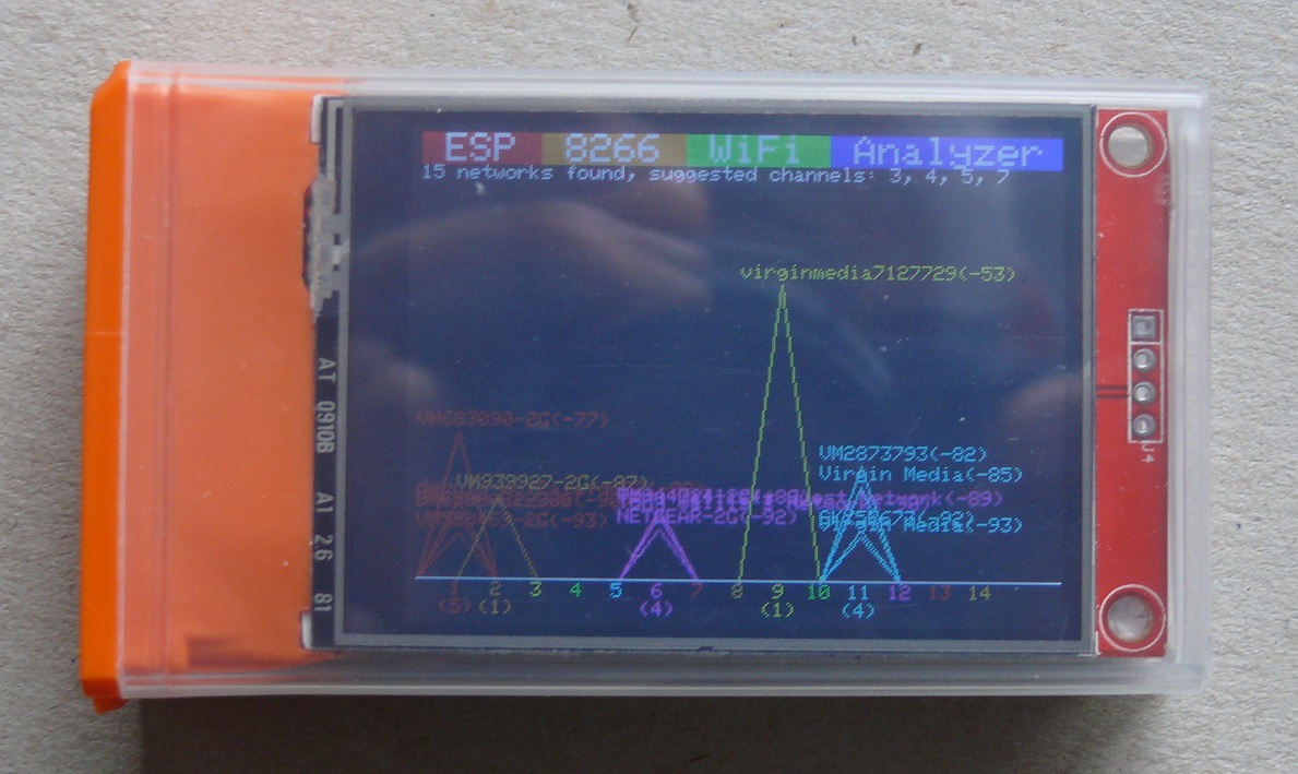
TicTac Super Wifi Analyser, ESP-12, ESP8266
This project builds on the original moononournation code and the concept of using a TicTac box as an enclosure.
However instead of using a button to kick off the readings this uses the touch panel that comes with a TFT SPI display. The code has been modified to better control of the LED backlight and to put the display into sleep mode (as the display module needs to stay powered for the touch chip). The unit current in sleep is low enough for a 1000mah lipo to last several years. There is also battery charging and low voltage protection in place.
See the last step for a video of it working.
Parts:
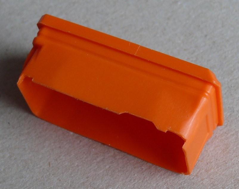
- 48g TicTac box
- ESP12 (preferably ESP-12F)
- 2.4” SPI TFT display
- Lipo charging module
- PNP transistor
- 3.3v low quiescent current, voltage regulator
- Associated resistors and capacitors (detail later)
Development
I thought I would outline the development path for this project. You can skip this section if you wish to get straight into making this.
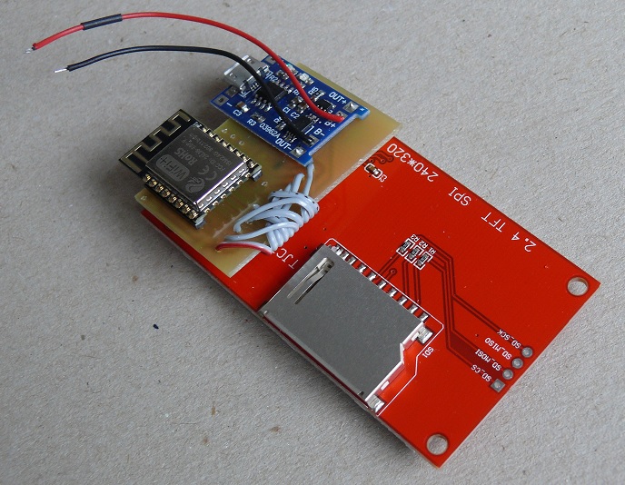
This is one of my first ESP8266 projects. I was taken with the neat concept of using a TicTac box as an enclosure for the Wifi analyser and decided to make one. Thank you: Portable-WiFi-Analyzer. I decided to use a larger 2.4” display – that came with a touch panel and on a PCB with pins that would be easier to connect to.
When I started the build I explored arrangements that would have the ESP12 aerial clear of the electronics. The only option was for it to be inside the cap. I also wanted the charger module under the dispenser. The question then was where to locate the ‘on button’? I did not want to make a hole in the back of the case. The top cap would be best – but there is no room if I have the two modules there.
This led to the idea of using the touch panel as the on button. I noticed one of the display connectors was labelled ‘T_IRQ’ – that looked encouraging. The touch chip is a XPT2046. And yes to my delight is has an auto sleep mode and pulls the T_IRQ low if the panel is touched. This is ideal to replace the push switch and can simply be connected to the ESP12 reset.
I should have mentioned that the code runs several scans for wifi networks and then removes power to the display and puts the ESP12 into deep sleep – that is woken up by a reset input.
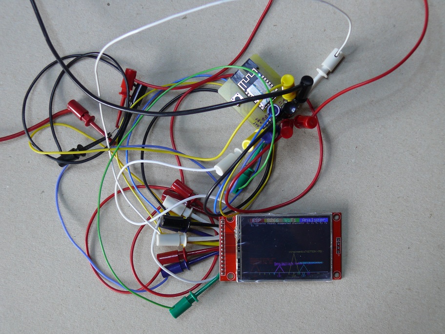
So with this concept clear, I wired it up, using a NodeMcu – and it didn’t work! So there was a bit more work to do. I was also conscious that I could not check the sleep current with the NodeMcu because of the on-board USB chip and high quiescent current voltage regulator. I also wanted a system for easily programming ESP12’s. This led to my making an ESP12 breakout board/development system that could be programmed as easily as the NodeMCU, but using a FTDI programmer. This way the regulator and USB chip is separate. See: ESP-12E and ESP-12F Programming and Breakout Board
Then I wired it up using my new board holding an ESP-12F – and it worked. The only change I had made was to short out the voltage regulator on the display module so all was driven at 3.3v. I started doing my code mods, particularly code to put the display chip (ILI9341) into sleep mode as this and the touch panel chip would need to powered (in sleep mode) when the ESP module is also in sleep. I then checked the sleep current. This was 90uA. So a 1000mah battery would last a year. Good start.
Then I removed the voltage regulator on the display module. It would have been enough to have just lifted the ground pin. Now the system sleep current was 32uA. I still had to add a 3.3v regulator but knew one with just 2uA quiescent current. So now we are looking at 3 years battery life!
I also wanted to mount the components as much as possible on a PCB to make the wiring neater. So at this point I went ahead with a PCB design for the unit. I would have liked to have connected directly to the display module pins. This was going to be pretty difficult so I opted to hard wire from the PCB to the display module.
I did a bit more tinkering with the code. I added a sleep notification – filling the screen in black and printing ZZZ before going to sleep. I also delayed the turning on of the LED backlight until the screen had been filled. This avoids the white flash at the start of the original code. I did similar mods at the end turning the LEDs off before putting the display to sleep.
You might be wondering how to measure uA. Dead easy! Put a 1k resistor in series with the positive power lead. Short this out with a jumper lead so the system can run. Then, when it is in sleep mode remove the jumper lead and measure the voltage drop across the resistor. With 1k resistor 100mv means 100uA. If the voltage drop is too great I use a lower value resistance. I have used this method to measure single figure nA using a 1m resistor on other systems with really low sleep currents.
Construction
PCB or hard wire?
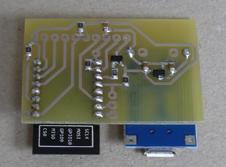
The unit I built here uses a PCB to hold the ESP12F and charger modules and the voltage regulator and PNP transistor and the associated capacitors and pull-up resistors. This is the neatest route, but requires PCB etching and SMD soldering equipment. However the system could be made by wiring the modules directly and putting the voltage regulator and PNP transistor onto a piece of stripboard – as was the case in the earlier TicTac project (linked earlier).
If you decide to go with the PCB option you may wish to also make my ESP12 programming board, especially if you plan to do more projects with the ESP12 boards.
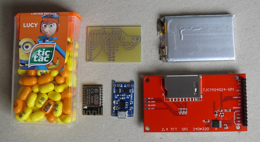
Parts list:
- 49g TicTac box
- ESP-12F (or ESP-12E) Note the ESP-12F has better range, otherwise same as ESP-12E
- 2.4” SPI TFT display with ILI9341 driver and touch e.g. TJCTW24024-SPI
- Charger module – see photo
- 2mm pin-strip (optional but worth using)
- PNP transistor in SOT23 format. I used BCW30 but any other with more than 100ma capability and DC gain>200 should be OK.
- 3v3 250ma(min) regulator in SOT23 format. I used Microchip MCP1703T-33002E/CB. Others will work but check their quiescent current. (suggest less than 30uA).
- Resistors (all 0805 size)
- 10k 4off
- 3k3 1 off
- Capacitors (all 0805 size)
- 2n2 2 off
- 0.1u 1 off
- PCB as WiFiAnalyserArtwork.docx file attached.
- Single cell LiPo battery. Capacity 400-1000mahr - that will fit in the case. 400mahr is plenty big enough.
For the non-PCB option use leaded equivalents, resistors ¼W and above are fine, and capacitors with working voltage of 5v or greater.
When making the PCB - drill the holes at 0.8mm. If you have a keen eye - the ESP12 2mm pin-strip holes can be 0.7mm for better support.
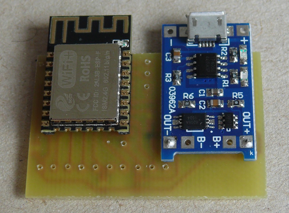
Component placement:
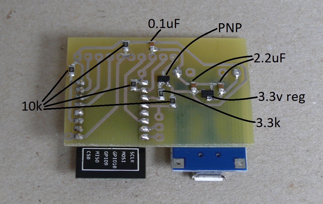
When assembling the PCB do the resistors and capacitors first, then the regulator and PNP transistor, followed by the charger module and the pin-strip for the ESP12. I didn’t solder the ESP12 in place as it is firm enough pressed onto the pin-strip, and it is easier to reprogram off the board. You will notice that the PCB has connectors for TX, RX, GPIO 0, Reset and ground if you ever want to reprogram in-situ. Note that a button will be required to pull GPIO low. Reset can be pulled low by touching the display. A button could be used but only if the wire to the display T_IRQ is disconnected.
Wiring
Before wiring the display to the circuit board remove the regulator i1 and put a blob of solder on J1 that then replaces this. Afterwards it should look like:
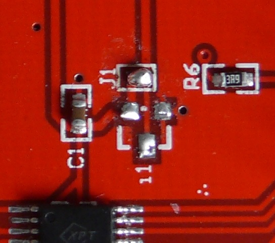
Then either remove the pin-strip or cut the pins short. The best way to remove the pin-strip is one pin at a time. Apply a soldering iron to one side while pulling the pin with pliers on the other.
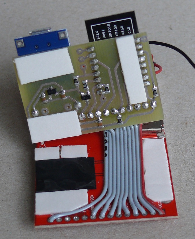
Now the wiring can start, beginning with connecting ribbon cable to the display. Cut around a 7-8cm length of PC ribbon cable and select 10 ways. Trim 9 of the ways back 10mm leaving one longer one at one edge for the T-IRQ pin. The rest can then be splayed out to where they will be soldered and trimmed a bit more where necessary.
I placed and soldered one lead at a time starting with VCC.
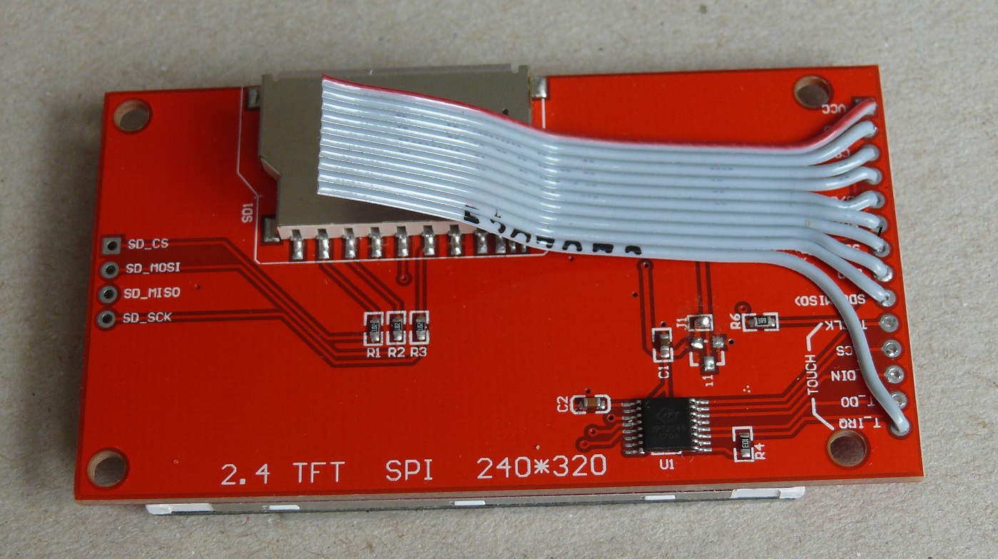
Place the PCB where it needs to be in relation to the display. Then, one at a time, trim the wires to 5mm or so longer than required and strip 2mm insulation, tin the end and solder in place. The wire routing goes as follows (counting pin numbers from VCC):
| Display | PCB | Comment |
| 1 | 1 | VCC |
| 2 | 8 | GND |
| 3 | 9 | CS |
| 4 | 5 | RESET |
| 5 | 7 | D/C |
| 6 | 2 | SDI(MOSI) |
| 7 | 4 | SCK |
| 8 | 10 | LED |
| 9 | 3 | SDO(MISO) |
| 10 | 6 | T_IRQ |
Now all that is left is to connect the battery and program the ESP12. If programming in-situ connect the battery now. If programming off the board connect the battery afterwards.
Programming
Download the code: ESP8266WiFiAnalMod.ino file, create a folder called ‘ESP8266WiFiAnalMod’ in your Arduino sketches folder and move the file to this.
Start the Arduino IDE (download and install from Arduino.cc if necessary) and add the ESP board details if you don’t have them (see: Sparkfun).
Load the code (File>Sketchbook>... ESP8266WiFiAnalMod).
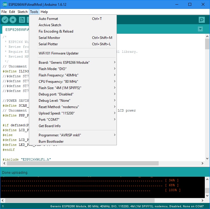
Then set the programming details (Tools):
Select board: Generic ESP8266 Module
See below for the rest of the settings. Select Reset method: “nodemcu” if using a programmer with the automated drive of the reset and GPIO0. Otherwise set to “ck” if programming in-situ or by direct connection to a USB to serial converter.
The Port number is likely to be different.
If you want to program in-situ you will need to solder wires to a switch to pull GPIO 0 low and connect to the Tx and Rx – see below:
An easier option is to use a programming board:ESP-12E and ESP-12F Programming and Breakout Board
If programming in-situ connect as below. Note if the display is connected Reset can be activated by the touch screen, otherwise a switch is needed from Reset to GND. Power is needed to the board, best by applying 3.7v to the OUT+ and OUT- pins. If using a battery the charger needs to be reset by briefly plugging in a USB lead.
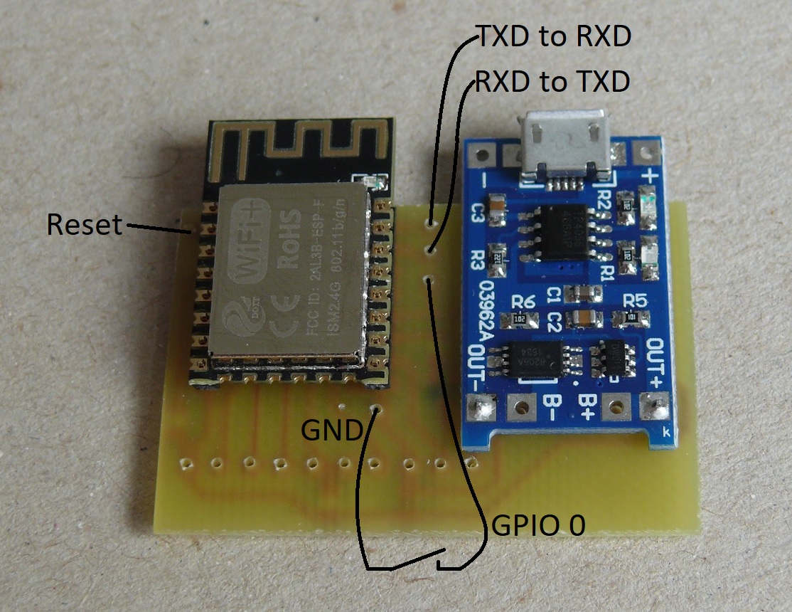
If setting the programming mode manually pull reset low (touch screen), pull GPIO 0 low and while low release the reset. Now click the download button. The programming should proceed.
If using the programming and breakout board just attach the FTDI USB serial converter, apply 3.3v power to the programming board and click download.
Final Assembly and Testing
Now is a good time for a preliminary test. If the ESP12 was programmed in-situ it should be working - just lightly touch the screen and it should start. If programmed off the unit - insert the ESP12 and wire up the battery and it should be working.
I disconnected the battery while going through the final assembly partly for convenience and partly to avoid any unintended short circuit.
The display will sandwich neatly between the cap and the bottom of the case. The raised section in the base nicely holds the screen to the box side.
The circuit board has to be fixed to the display board in order to both fit inside the cap and present the USB charging socket. When the required relationship between the board positions is seen then place double sided tape (the 1mm thick type) to both boards. This will give a 2mm clearance that should avoid any electrical contact. I placed some insulating tape covering the display electronics as a precaution:
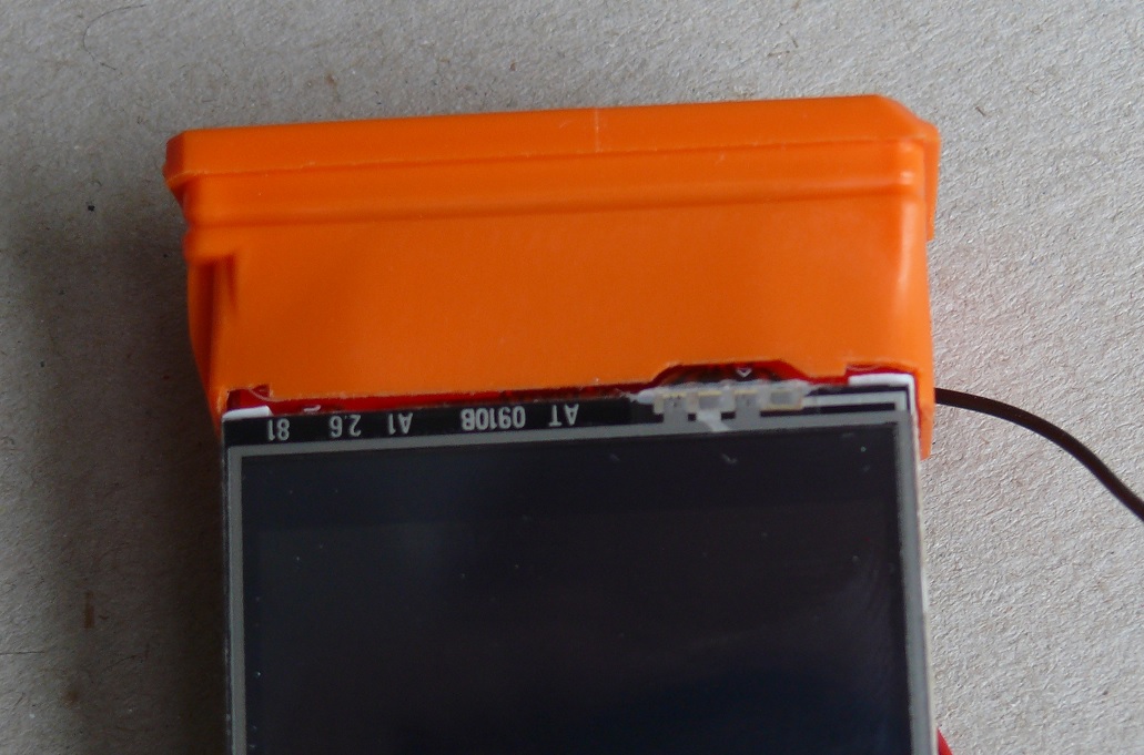
Next we need to take around 2mm off the top cap. I made this a snug fit to the screen with extra bits cut out for the touch screen ribbon cable and the screen plastic mount. See below:
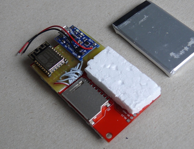
Lastly we need to place the battery and use this to hold the display against the box side. I used an old piece of polystyrene foam and cut and sanded it the to required thickness. I stuck this to the display PCB using thin double sided tape and used a couple of smaller pieces of tape to stop the battery sliding about.
When you have connected it all up and find that nothing happens, don’t worry (yet). The battery protection circuit on the charger module has to be reset. This is done by connecting it via a micro USB lead to a 5v supply. A few seconds is long enough.
And now you have a useful device that shows the power of the ESP8266 systems, and in my case led me to changing my WiFi channel as it detected 5 others on the same one!
I hope you enjoy this lovely project.
Mike